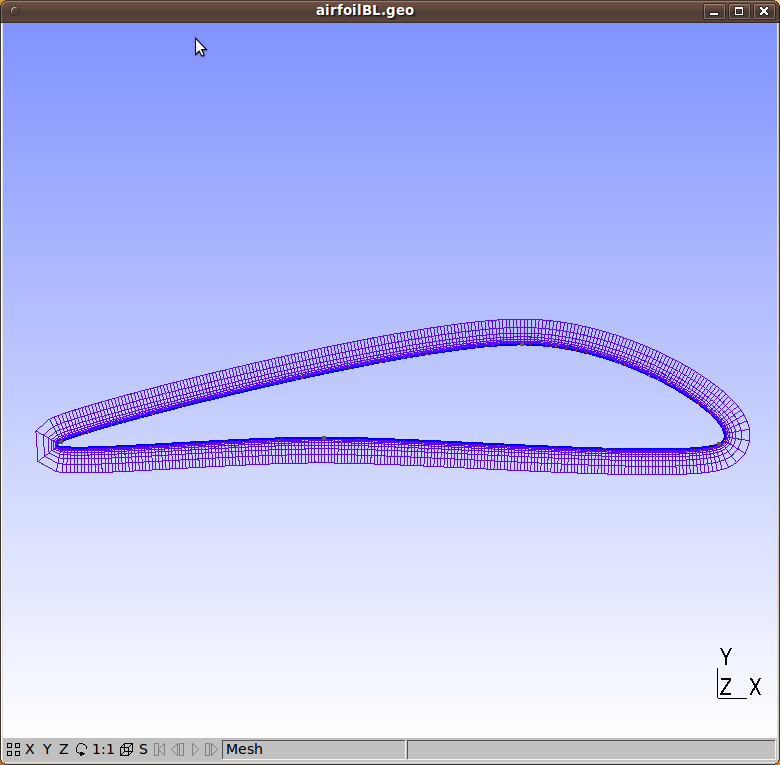

Only one boundary setting bbject/Field can be applied, but multiple boundary faces can be selected.ĢD meshing can get a result and shown up in taskpanel.Īlthough solid mechanics does not need a boundary layer, but it should not hurt. but anyway, you can substitute the coarse mesh generated by FEM/CFD workbench with some better one after the initial evaluation in GUI.Īlso mentioned, OpenFOAM CFD workbench use cfmesh and snappyHexMesh of OpenFOAM for boundarlyer refinement. Gmsh boundary meshing is not robust like commercial tool like Ansys workbench, so it may fail for complex geometry. This function is built on his work of FemMeshRegion, Thanks for bernd. Now I am turning into coding, a new class "FemMeshBoundaryLayer" is added, holding setup information. The boundary layer is hard to see, meshing bisect may illustrate it better. Gmsh 3d boundarylayer.png (376.39 KiB) Viewed 6650 times write ( 'naca_boundary_layer_2d.msh' ) 144 145 if '-nopopup' not in sys. optimize ( 'HighOrderFastCurving' ) 141 gmsh. generate ( 2 ) 136 137 # 2nd order + fast curving of the boundary layer + optimization 138 if order2 : 139 gmsh. setAsBoundaryLayer (f ) 133 134 # generate the mesh 135 gmsh. setNumbers (f, 'FanPointsList', ) 131 132 gmsh. setNumber ( 'Mesh.BoundaryLayerFanElements', 7 ) 130 gmsh. setNumber (f, 'Thickness', 0.01 ) 127 if not rounded : 128 # create a fan at the trailing edge 129 gmsh. setNumbers (f, 'CurvesList', curv ) 123 gmsh. synchronize () 104 105 else : 106 # in 2D, boundary layers can also be specified as a meshing constraint, 107 # through the BoundaryLayer field this is quite a bit more general, as it 108 # handles intersections between several boundary layers, fans, etc. addCurveLoop ( for c in extbl ]) 91 92 # connect it with the exterior surface 93 p1 = gmsh. getEntities ( 1 ), 87 * N, d, True ) 88 89 # create curve loop with "top" curves of the boundary layer 90 cl2 = gmsh.

append (d - (-d ) * r **i ) 85 print (d ) 86 extbl = gmsh. synchronize () 77 # a boundary layer can be created through extrusion using the built-in CAD 78 # kernel: this creates topological entities that will be filled with a 79 # discrete geometry (a mesh extruded along the boundary normals) during mesh 80 # generation 81 N = 10 # number of layers 82 r = 2 # ratio 83 d = # thickness of first layer 84 for i in range ( 1, N ): d. addCurveLoop (curv ) 74 75 if by_extrusion : 76 gmsh. addLine (pt, pts )) 69 70 # rotate the profile 71 gmsh. addCircleArc (pts, c, pts )) 65 else : 66 pt = gmsh. addSpline (pts )) 60 61 if rounded : 62 # circle as trailing edge 63 c = gmsh. addPoint (naca, -naca, 0, lc1 )) 57 pts. 11 12 # create the boundary layer by extrusion, or as a mesh constraint? 13 by_extrusion = False 14 15 # rounded trailing edge? 16 rounded = True 17 18 # base mesh sizes 19 fact = 1 20 lc1 = 0.01 * fact 21 lc2 = 0.3 * fact 22 23 # generate curved mesh? 24 order2 = False 25 26 # xy coordinates of top part of NACA 0012 profile 27 naca = 49 50 # create profile from points 51 pts = 52 l = len (naca ) 53 for i in range ( 0, l // 2 ): 54 pts. add ( "NACA 0012" ) 8 9 # incidence angle 10 incidence = -math.
#GMSH BOUNDARY LAYER FAN CODE#
See also the last Fossies "Diffs" side-by-side code changes report for "naca_boundary_layer_2d.py": 4.9.5_vs_4.10.0.ġ import gmsh 2 import sys 3 import math 4 import numpy as np 5 6 gmsh.
#GMSH BOUNDARY LAYER FAN DOWNLOAD#
As a special service "Fossies" has tried to format the requested source page into HTML format using (guessed) Python source code syntax highlighting (style: standard) with prefixed line numbers.Īlternatively you can here view or download the uninterpreted source code file.


 0 kommentar(er)
